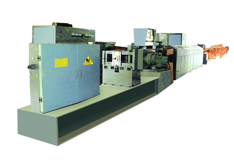
Unit Configuration and Performance Overview
This unit is a specialized equipment designed for producing cold-rolled double-sided ribbed steel bars. The production line is capable of processing Q235 hot-rolled round wire rods (Figure 1) with diameters ranging from ��6.5 mm to ��14 mm, and cold-rolling them into ribbed bars featuring crescent moon-shaped ribs on both sides (Figure 2).
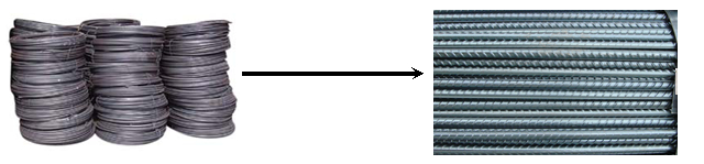
Figure 1 (wire rods in coil) Figure 2(crescent moon-shaped ribs on both sides)
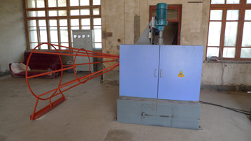
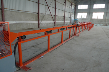
The complete set of equipment consists of a pay-off stand, straightening and guiding cage, descaler, pre-rolling mill, main rolling mill, straightener, heating device, temperature measuring unit, shearing machine, sliding guide, dual-side receiving unit, pneumatic automatic leveling pusher, and take-up machine. The unit is designed for continuous operation, with the entire system controlled by a PLC.
Below is a brief description of the structure and performance of each component
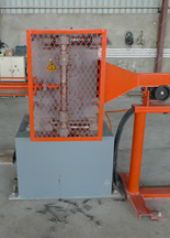
(1) The pay-off stand ensures the high-speed operation of the unit.
It consists of dual payoff tubes: one is the working stand, and the other is the storage stand. While one tube is paying off the wire rod, the other can be pre-loaded with a new coil. When the coil on the working stand is depleted, the tail end of that coil and the head end of the coil on the storage stand are welded together and ground. Production can then continue without stopping, and the now-empty stand can be pre-loaded. This pre-loading design concept improves efficiency by eliminating downtime for loading.
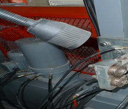
(2) Straightening Cage and Motorized Vertical Descaling Machine
The straightening cage is welded from ribbed steel bars. Its funnel-shaped structure transforms the steel bars from a coiled state into straight, spiraled bars, thereby ensuring that the reinforcement is essentially straight before entering the descaling machine. This guarantees the high-speed and reliable operation of the equipment.
The dust-proof descaling machine consists of five pulleys. Its primary function is to repeatedly bend hot-rolled coiled rods using these five descaling wheels, thereby removing the surface oxide scale. This improves the surface quality of the steel bars and plays a significant role in reducing wear on the rolling mill rolls. The base is welded from steel plate assemblies. To save space, it can be installed on the same base as the main machine.
(3) Pre-finishing Rolling Mill
The pre-finishing rolling mill flattens and reduces the diameter of the reinforcement, preparing it for thread rolling in the main rolling mill. This mill operates as a passive rolling mill.
(4) Main Rolling Mill
The main rolling mill is the final step in forming ribbed steel bars. It withstands substantial forces and requires high machining precision. The mill offers the following advantages:
1.Center Self-Alignment (Domestically Exclusive) �C No adjustment is needed for the mill center, regardless of the size or wear condition of the rollers.
2.Extended Roller Service Life �C A single roller set can process over ten thousand tons of steel.
3.Easy Roller Replacement (Domestically Exclusive) �C Features a slide-drawer replacement system, allowing completion within 10 minutes.
4.Automatic Cooling System (Domestically Exclusive) �C Integrated exclusively into the main rolling mill.
5.High Automation (Domestically Exclusive) �C Fully automatic concentric alignment; no adjustment required when changing reinforcement entry/exit guides. This represents world-leading technology.
6.Integrated High-Precision Guide (Domestically Exclusive) �C A single guide unit adjusts vertically, horizontally, and laterally.
7.Proprietary CNC Automatic Grease Lubrication System (Domestically Exclusive) �C Prevents bearing damage caused by delayed manual lubrication
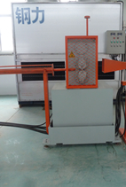
(5) Control Console
The sole control console integrates the operation of the rolling mill, heating, cutting, blanking, material receiving, and the swing-and-leveling mechanism for finished bars onto a single panel. This achieves true centralized and unified control. By mounting the control head directly on the mill itself, it saves valuable floor space in the workshop, allowing for the installation of more equipment within limited factory areas. The control system utilizes PLC program control with a touchscreen display, which enhances operational stability and provides intuitive interaction. Fault locations can be directly identified and displayed on the touchscreen.
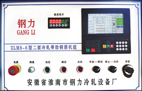
Note: This device adopts an infrared non-contact temperature measurement method, utilizing optical fiber transmission. It features strong anti-interference capability and displays temperature digitally.
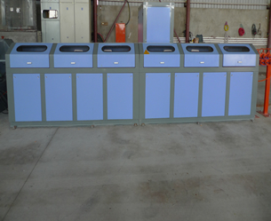
(6) Heating Cabinet (see illustration Below)
The primary operating cost for this equipment set is electricity consumption. The performance of the reinforcement heating equipment is directly reflected in its power consumption index. The adoption of high-performance intermediate-frequency or super audio-frequency heating equipment can save 20 to 50 kWh per ton in electricity costs. It is required to utilize high-performance RBGT modules, which offer high electrical conversion efficiency. The heating equipment operates safely, reliably, and is environmentally friendly.
(7) Cutting
The cutting process employs a flying shear independently developed by our factory. It features low cutting power consumption, rapid response, low failure rate, and is maintenance-free. Through years of improvements, the technology is highly mature and delivers industry-leading performance.
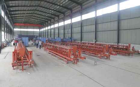
(8) Dual-side Tipping and Discharging System
This system operates in a dual-group cyclic mode (A �� B �� A), allowing for separate parameter settings and independent collecting/bundling operations to meet the requirement of uninterrupted bundling.
The dual receiving racks (left and right) are designed to minimize downtime for bundling and enhance production efficiency. After the reinforcement bars are cut, they fall from the tipping plate into the U-shaped receiving unit for storage, providing a reliable method for material collection.
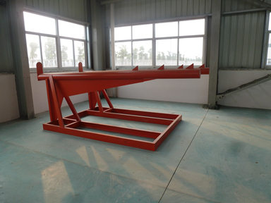
(9) Leveling Device (Versatile Leveling)
When reinforcement bars fall into the collection rack, they are often uneven in length and require leveling. Our factory has designed a pneumatic automatic leveling device that can replace manual leveling, eliminate safety hazards, and allow the operator to set the frequency of leveling based on the number of bars.
Disadvantages of the single-drive system compared to the dual-drive system for two-side cold-rolled ribbed steel bar production lines:
1.Butt welding is less secure, leading to a higher risk of bar breakage;
2.Each time the bar is threaded through, 10�C20 meters of scrap material are generated;
3.The rollers bear excessive load and are prone to damage.
|
Product name
|
unit of measurement
|
Cold rolled two ribbed reinforced bar units
|
Cold rolled two ribbed reinforced bar units
|
Cold rolled two ribbed reinforced bar units
|
Cold rolled two ribbed reinforced bar units
|
Cold rolled two ribbed reinforced bar units
|
Cold rolled two ribbed reinforced bar units
|
|
Model
|
|
LMD10-9A
|
LMD12-10B
|
LMD12-10C
|
LMS12-10A
|
LMS12-10B
|
LMS16-14C
|
|
Diameter of raw material(before machining )
|
mm
|
��6-10
|
��6-12
|
��6-12
|
��6-12
|
��6-12
|
��6-14
|
|
Diameter of finished product(after machining )
|
mm
|
��5-9
|
��5-11
|
��5-11
|
��5-11
|
��5-11
|
��5-13
|
|
Roller speed
|
m/min
|
120
|
150
|
180
|
150
|
180
|
200
|
|
Predetermined length
|
m
|
1��99
|
1��99
|
1��99
|
1��99
|
1��99
|
1��99
|
|
Length of unloading chute
|
m
|
6��12
|
6��12
|
6��12
|
6��12
|
6��12
|
6��12
|
|
Unloading direction
|
|
Single-direction unloading
|
Two-sided unloading
|
Two-sided unloading
|
Two-sided unloading
|
Two-sided unloading
|
Two-sided unloading
|
|
Unloading and sliding mode
|
|
360-degree rotation
|
360-degree rotation
|
360-degree rotation
|
360-degree rotation
|
360-degree rotation
|
360-degree rotation
|
|
Row spacing of bars
|
mm
|
Optional accessories 5~20
|
|
Length of Secondarily Collected Material
|
m
|
Optional length 6~12
|
|
Material Leveling Method
|
|
Pneumatic automatic leveling
|
|
Speed adjustment
|
|
Adjust speed
|
Variable frequency
|
Variable frequency
|
Variable frequency
|
Variable frequency
|
Variable frequency
|
|
Control mode
|
|
Text panel��PLC
|
Text panel��PLC
|
Touch screen��PLC
|
Touch screen��PLC
|
Touch screen��PLC
|
Touch screen��PLC
|
|
Cutting error
|
mm
|
��4
|
��2
|
��2
|
��2
|
��2
|
��2
|
|
Main motor power
|
KW
|
75KW
|
90KW
|
132KW
|
75KW��90KW
|
90KW��110KW
|
110KW��132KW
|
|
Heating power
|
KW
|
300
|
400��500��
|
500��600��
|
500
|
600
|
800
|
|
Total power
|
KW
|
400
|
500
|
650
|
670
|
800
|
1050
|
|
Total weight (approx.)
|
Kg
|
6000
|
8000
|
14000
|
9000
|
16000
|
20000
|
|
Min. Working Area (with pay-off)
|
Length �� width��height��m��
|
40��5��6
|
50��5��6
|
50��5��6
|
50��5��6
|
55��5��6
|
70��5��6
|
|
Pay-off Stand
|
|
Dual set
|
|
Wire Straightener
|
|
Optional Accessories
|
|
Rolling mill
|
|
top synchronous pressing
|
Electric automatic tuning
|
electric automatic self-alignment
|
electric automatic self-alignment
|
electric automatic self-alignment
|
electric automatic self-alignment
|
|
Rolling times
|
|
2
|
2
|
2
|
2
|
2
|
2
|
|
Roll size
|
mm
|
Active mill��228
+Passive mill��155
|
Active mill 228��Passive mill��210
|
Active mill��228+Passive mill��210
|
Active mill��228��Active mill��210
|
Active mill��228��Active mill��210
|
Main mill��228��Active mill��210
|
|
Straightening method
|
|
In-line Straight Bar
|
In-line Straight Bar
|
In-line Straight Bar
|
In-line Straight Bar
|
In-line Straight Bar
|
In-line Straight Bar
|
|
Take-up Machine
|
|
Optional Accessories
|
|
Output of �� 6 mm rebars
|
Kg
|
1598 kg/h
|
2000 kg/h
|
2398 kg/h
|
2000 kg/h
|
2398 kg/h
|
2660 kg/h
|
|
Output of �� 7 mm rebars
|
Kg
|
2170 kg /h
|
2700 Kg/h
|
3250 kg/h
|
2700 kg/h
|
3250 Kg/h
|
3620 kg/h
|
|
Output of ��8 mm rebars
|
Kg
|
2800 kg /h
|
3555 kg/h
|
4200 kg/h
|
3555 kg/h
|
4200 kg/h
|
4728 kg/h
|
|
Output of ��9 mm rebars
|
Kg
|
3500 kg /h
|
4400 Kg/h
|
5000 kg/h
|
440 Kg/h
|
5000 kg/h
|
5988 kg/h
|
|
Output of ��10 mm rebars
|
Kg
|
|
5000 kg/h
|
5500 kg/h
|
5000 kg/h
|
5500 kg/h
|
6000 kg/h
|
|
Output of ��11 mm rebars
|
Kg
|
|
5500 kg/h
|
6000 kg/h
|
5500 kg/h
|
6000 kg/h
|
7500 kg/h
|
|
Output of ��12 mm rebars
|
Kg
|
|
|
|
|
|
7000 kg/h
|
|
Output of ��13 mm rebars
|
Kg
|
|
|
|
|
|
8000 kg/h
|
|
Output of ��14 mm rebars
|
Kg
|
|
|
|
|
|
7000 kg/h
|
|
Output of ��15 mm rebars
|
Kg
|
|
|
|
|
|
8000 kg/h
|
|
Personnel Required for Complete Operation
|
persons per line
|
3
|
4
|
4
|
4
|
4
|
4
|