Our factory has successfully mass-produced the ZLM series double-sided cold-rolled ribbed steel bar production line. This equipment can process Q235 hot-rolled coiled steel bars with diameters ranging from ��6.5 to ��14mm into double-sided ribbed steel bars with crescent-shaped ribs. It has completely resolved the long-standing industry challenge of substandard elongation in cold-rolled ribbed steel bars.
The double-sided cold-rolled ribbed steel bars produced by this equipment exceed all technical standards of hot-rolled HRB400 (Grade III steel) and HRB500 (Grade IV steel) as per national standards. The steel bars exhibit no springback, maintain elongation without decline, and serve as an efficient alternative to Grade III steel. Additionally, they help conserve expensive metals such as vanadium (V), niobium (Nb), and titanium (Ti) used in Grade III and Grade IV steel production.
The equipment features user-friendly operation, with full automation across all processes including wire feeding, steel bar rolling, strength control, elongation regulation, fixed-length cutting, double-sided discharging, automatic leveling, and coiled wire collection. Changing to different steel bar specifications does not require replacing the rolls; only simple adjustments to the machine are needed. The production process requires no lubricating powder or cooling fluid, resulting in low production costs. This is a highly efficient coiling-type double-sided cold-rolled ribbed steel bar production line.
Structural Features:
�� Exclusive Design:
Our factory��s high-end equipment adopts an active rolling mill design for both the main and auxiliary rolling mills. The rolling force is evenly distributed, reducing the stress on the rollers by half. As a result, the service life of our rollers is twice that of rollers of the same quality on the market. (In contrast, most market equipment uses one set of main rollers to drive another set of passive rollers, causing excessive stress on the main rollers and making them prone to damage.)
Changing to different specifications of steel bars does not require adjustment of the frame or the feeding position, which never needs realignment. This minimizes the risk of defective products caused by improper manual adjustments.
The rollers employ a constant-tension self-locking mechanism, solving the problems of rollers being prone to breakage, difficult to secure, and hard to disassemble.
The drive motor controller uses the widely recognized energy-saving product��the frequency converter��paired with a squirrel-cage drive motor, maximizing energy efficiency and minimizing failure rates.
��Upper and Lower Synchronous Loading Design��: The roller center never requires adjustment (a feature unique to our equipment).
��Dual Pay-off Stand and Whole-line System Design��: Manual feeding is now a thing of the past, reducing downtime caused by threading and welding, thereby improving efficiency.
��Fully Digital Control��: Simple operation and easy adjustment of dimensions.
��All Processes��Descaling, Cold Rolling, Transmission, Guiding, and Cutting��Utilize Rolling Bearings��: Long service life and excellent interchangeability.
��Stepless Speed Adjustment Allows Smooth Passage of Round Bars Even After Welding��: No material waste.
��Integrated Steel Structure Design��: No concrete foundation required; production can begin after simple leveling.
��Main Machine Gears Made of 20CrMnMo��: Carburized, quenched, and ground gears ensure low noise, high load capacity, and are equipped with a self-circulating water-cooling system for temperature control. Stable performance over 10 years of long-term operation with extended service life.
��No External Cooling Required��: Built-in circulating system eliminates the need for constructing a cooling pool��saving space and costs.
��Guide Nozzles Made of Wear-resistant Materials��: Helps reduce production costs.
When paired with tungsten carbide alloy rollers, the regrinding service life can exceed 10,000 tons, further enhancing the surface forming quality of steel bars.
Unit Configuration and Performance Overview
This unit is a specialized equipment designed for producing cold-rolled double-sided ribbed steel bars. The production line is capable of processing Q235 hot-rolled round wire rods (Figure 1) with diameters ranging from ��6.5 mm to ��14 mm, and cold-rolling them into ribbed bars featuring crescent moon-shaped ribs on both sides (Figure 2).

Figure 1 Figure 2
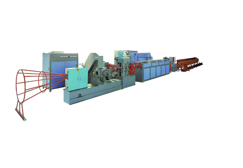
The complete set of equipment consists of a pay-off stand, straightening and guiding cage, descaler, pre-rolling mill, main rolling mill, straightener, heating device, temperature measuring unit, shearing machine, sliding guide, dual-side receiving unit, pneumatic automatic leveling pusher, and take-up machine. The unit is designed for continuous operation, with the entire system controlled by a PLC.

Below is a brief description of the structure and performance of each component��
(1) The pay-off stand ensures the high-speed operation of the unit.
It consists of dual payoff tubes: one is the working stand, and the other is the storage stand. While one tube is paying off the wire rod, the other can be pre-loaded with a new coil. When the coil on the working stand is depleted, the tail end of that coil and the head end of the coil on the storage stand are welded together and ground. Production can then continue without stopping, and the now-empty stand can be pre-loaded. This pre-loading design concept improves efficiency by eliminating downtime for loading.
(2) Straightening Cage
The straightening cage is welded from steel rebar. Its funnel-shaped design transforms the steel bars from a coiled form into straight, spiraled strands, ensuring that the steel bars are essentially straight before entering the descaler. This guarantees high-speed and reliable operation of the equipment.
(3) Descaler
The descaler is equipped with five descaling wheels. The new product features electric pressure adjustment, dust-proof doors, an inclined chute for discharging scale, and a scale collection bag, creating a dust-free descaling concept.
(4) Auxiliary Rolling Mill
The flattening mill adopts driven rollers and incorporates a cooling system. It is powered by a Y2 energy-efficient motor driven by an inverter, ensuring energy savings and high efficiency.
(5) Main Rolling Mill
The new main rolling mill features a fully sealed design, resolving previous issues such as jamming during pressure application. The main reduction gearbox and the reversing gearbox are integrated into a single unit, eliminating vulnerable parts like cross sliders. The gearbox gears are fully ground, ensuring smooth and noiseless operation. The speed is significantly increased to 180�C200 meters per minute.
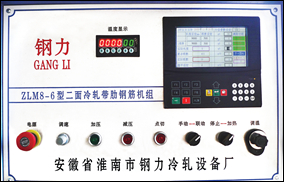
(6) Control Panel
The control system utilizes PLC programming with a touchscreen display, enhancing operational stability and user intuitiveness. The touchscreen displays fault locations, enabling quick and accurate troubleshooting.
Length measurement employs a high-resolution encoder to ensure precise cutting accuracy.
Speed adjustment: The main and auxiliary rolling mills are controlled by a single knob, simplifying operation.
(7) Heating Cabinet
The heating equipment is sourced from several of the largest domestic manufacturers for customers to choose from. The cabinet is available in multiple universal specifications, and high-energy-saving heating equipment is also offered, allowing customers to freely select their configuration. As heating equipment varies significantly in power consumption and quality, customers are reminded to make their choices carefully.
(8) Cutting
The new cutting system employs a servo flying shear independently developed by our factory, utilizing imported servo motors. This effectively enhances the reliability of the flying shear and improves cutting accuracy. During acceleration or deceleration, the length of the steel bar cut remains consistent with that during constant speed operation. The cutting system features low power demand, fast response, and represents industry-leading technology.
(9) 360�� Rotating Discharge Chute System
This system adopts a dual-group cyclic working mode (A��B��C��D��A). The discharge rack features a 360�� rotating design, which prevents jamming and avoids common issues such as frequent adjustments and unstable material discharge.

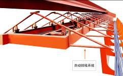
(10) arranging blanking system; (10) Arranged Discharge System
The innovative arranged discharge system automatically shifts the discharge rack left or right after steel bars are cut. This ensures that the bars land at varied positions, effectively reducing manual straightening caused by overlapping bars. It also minimizes quality inconsistencies in bundled bars due to significant temperature differentials.
(11) Receiving System
Dual receiving racks (left and right) are used for material collection. After cutting, the steel bars fall from the flip plate onto an inclined aligning rack and slide into a U-shaped receiving unit for storage, significantly improving work efficiency.
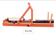
(12) Leveling Device
When steel bars collect in the gathering rack with uneven lengths, leveling is required. Our factory has designed a pneumatic automatic leveling device that replaces manual leveling, eliminates safety hazards, and can be set to activate after a specified number of bars accumulate.
|
Product name
|
unit of measurement
|
Cold rolled two ribbed reinforced bar units
|
Cold rolled two ribbed reinforced bar units
|
Cold rolled two ribbed reinforced bar units
|
Cold rolled two ribbed reinforced bar units
|
Cold rolled two ribbed reinforced bar units
|
Cold rolled two ribbed reinforced bar units
|
|
Model
|
|
LMD10-9A
|
LMD12-10B
|
LMD12-10C
|
LMS12-10A
|
LMS12-10B
|
LMS16-14C
|
|
Diameter of raw material(before machining )
|
mm
|
��6-10
|
��6-12
|
��6-12
|
��6-12
|
��6-12
|
��6-14
|
|
Diameter of finished product(after machining )
|
mm
|
��5-9
|
��5-11
|
��5-11
|
��5-11
|
��5-11
|
��5-13
|
|
Roller speed
|
m/min
|
120
|
150
|
180
|
150
|
180
|
200
|
|
Predetermined length
|
m
|
1��99
|
1��99
|
1��99
|
1��99
|
1��99
|
1��99
|
|
Length of unloading chute
|
m
|
6��12
|
6��12
|
6��12
|
6��12
|
6��12
|
6��12
|
|
Unloading direction
|
|
Single-direction unloading
|
Two-sided unloading
|
Two-sided unloading
|
Two-sided unloading
|
Two-sided unloading
|
Two-sided unloading
|
|
Unloading and sliding mode
|
|
360-degree rotation
|
360-degree rotation
|
360-degree rotation
|
360-degree rotation
|
360-degree rotation
|
360-degree rotation
|
|
Row spacing of bars
|
mm
|
Optional accessories 5~20
|
|
Length of Secondarily Collected Material
|
m
|
Optional length 6~12
|
|
Material Leveling Method
|
|
Pneumatic automatic leveling
|
|
Speed adjustment
|
|
Adjust speed
|
Variable frequency
|
Variable frequency
|
Variable frequency
|
Variable frequency
|
Variable frequency
|
|
Control mode
|
|
Text panel��PLC
|
Text panel��PLC
|
Touch screen��PLC
|
Touch screen��PLC
|
Touch screen��PLC
|
Touch screen��PLC
|
|
Cutting error
|
mm
|
��4
|
��2
|
��2
|
��2
|
��2
|
��2
|
|
Main motor power
|
KW
|
75KW
|
90KW
|
132KW
|
75KW��90KW
|
90KW��110KW
|
110KW��132KW
|
|
Heating power
|
KW
|
300
|
400��500��
|
500��600��
|
500
|
600
|
800
|
|
Total power
|
KW
|
400
|
500
|
650
|
670
|
800
|
1050
|
|
Total weight (approx.)
|
Kg
|
6000
|
8000
|
14000
|
9000
|
16000
|
20000
|
|
Min. Working Area (with pay-off)
|
Length �� width��height��m��
|
40��5��6
|
50��5��6
|
50��5��6
|
50��5��6
|
55��5��6
|
70��5��6
|
|
Pay-off Stand
|
|
Dual set
|
|
Wire Straightener
|
|
Optional Accessories
|
|
Rolling mill
|
|
top synchronous pressing
|
Electric automatic tuning
|
electric automatic self-alignment
|
electric automatic self-alignment
|
electric automatic self-alignment
|
electric automatic self-alignment
|
|
Rolling times
|
|
2
|
2
|
2
|
2
|
2
|
2
|
|
Roll size
|
mm
|
Active mill��228
+Passive mill��155
|
Active mill 228��Passive mill��210
|
Active mill��228+Passive mill��210
|
Active mill��228��Active mill��210
|
Active mill��228��Active mill��210
|
Main mill��228��Active mill��210
|
|
Straightening method
|
|
In-line Straight Bar
|
In-line Straight Bar
|
In-line Straight Bar
|
In-line Straight Bar
|
In-line Straight Bar
|
In-line Straight Bar
|
|
Take-up Machine
|
|
Optional Accessories
|
|
Output of �� 6 mm rebars
|
Kg
|
1598 kg/h
|
2000 kg/h
|
2398 kg/h
|
2000 kg/h
|
2398 kg/h
|
2660 kg/h
|
|
Output of �� 7 mm rebars
|
Kg
|
2170 kg /h
|
2700 Kg/h
|
3250 kg/h
|
2700 kg/h
|
3250 Kg/h
|
3620 kg/h
|
|
Output of ��8 mm rebars
|
Kg
|
2800 kg /h
|
3555 kg/h
|
4200 kg/h
|
3555 kg/h
|
4200 kg/h
|
4728 kg/h
|
|
Output of ��9 mm rebars
|
Kg
|
3500 kg /h
|
4400 Kg/h
|
5000 kg/h
|
440 Kg/h
|
5000 kg/h
|
5988 kg/h
|
|
Output of ��10 mm rebars
|
Kg
|
|
5000 kg/h
|
5500 kg/h
|
5000 kg/h
|
5500 kg/h
|
6000 kg/h
|
|
Output of ��11 mm rebars
|
Kg
|
|
5500 kg/h
|
6000 kg/h
|
5500 kg/h
|
6000 kg/h
|
7500 kg/h
|
|
Output of ��12 mm rebars
|
Kg
|
|
|
|
|
|
7000 kg/h
|
|
Output of ��13 mm rebars
|
Kg
|
|
|
|
|
|
8000 kg/h
|
|
Output of ��14 mm rebars
|
Kg
|
|
|
|
|
|
7000 kg/h
|
|
Output of ��15 mm rebars
|
Kg
|
|
|
|
|
|
8000 kg/h
|
|
Personnel Required for Complete Operation
|
persons per line
|
3
|
4
|
4
|
4
|
4
|
4
|
|
|
|
|
|
|
|
|
|
|